Introduction
The goal of this project was to determine to what extent yard tractors (or ‘port haulers’ colloquially) can be converted into autonomous vehicles in-house. These vehicles haul container carrying trailers from quayside to storage yard in the ports. The company was already developing a non-autonomous port hauler, but the team anticipated that autonomy would eventually become an entry to market requirement, so I decided to initiate this project. By developing an autonomy kit, retrofitting would also be made possible on older vehicles.
Software Development Approach
Early on a decision had to be made whether to develop from scratch or leverage open source. I was on the project full-time, while another engineer had half of his time dedicated to this project and others assisted on an ad-hoc basis. Given the small team, limited resources and the availability of the open source Robot Operating System (ROS) framework, I decided to pursue the open source route. This decision yielded rapid progress, greater number of features and higher quality software. Exposure to an established codebase and community yielded secondary benefits such as adoption of best practices, broader applicability, and better code maintainability.
Hardware Architecture and Approach
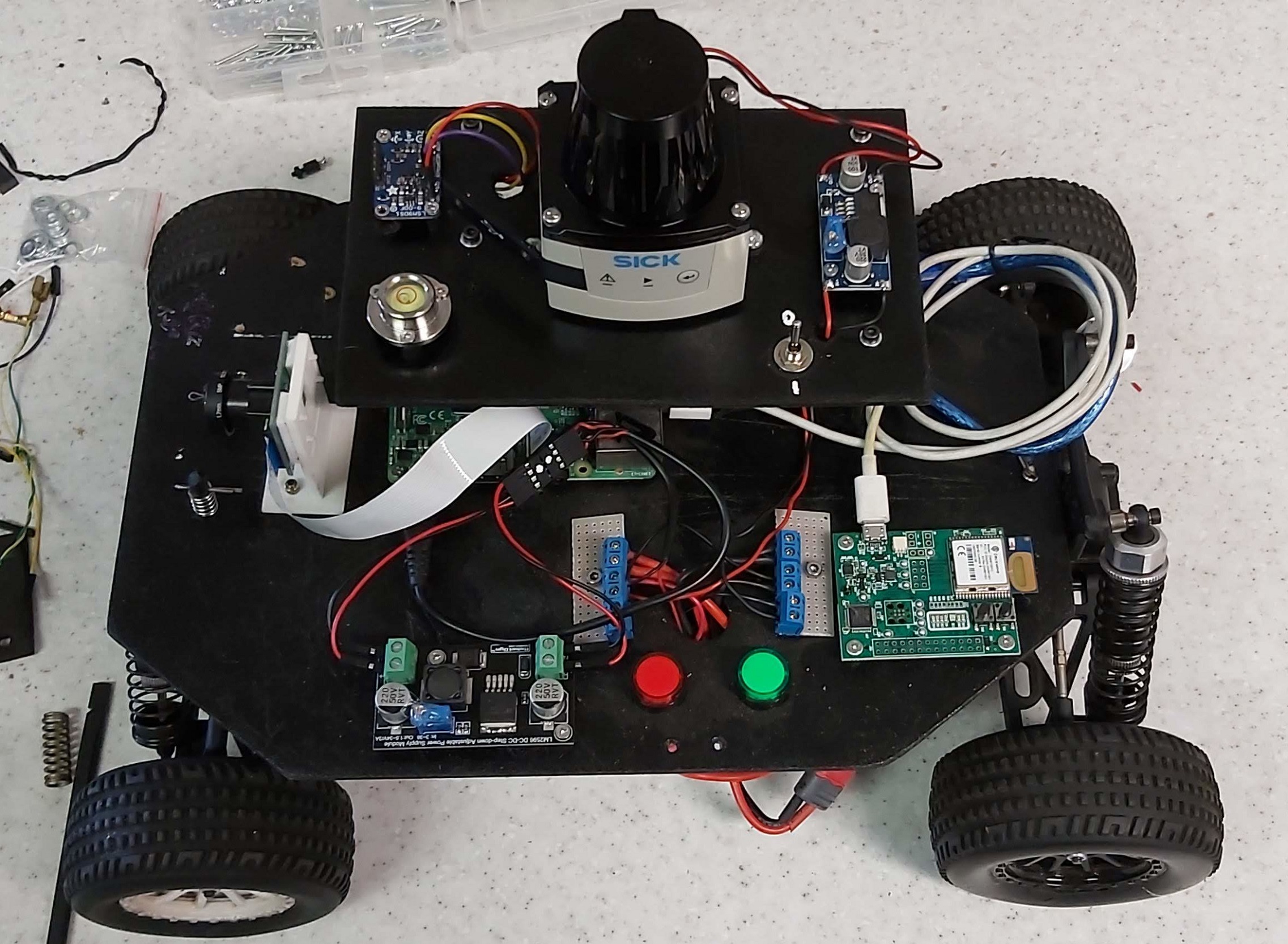
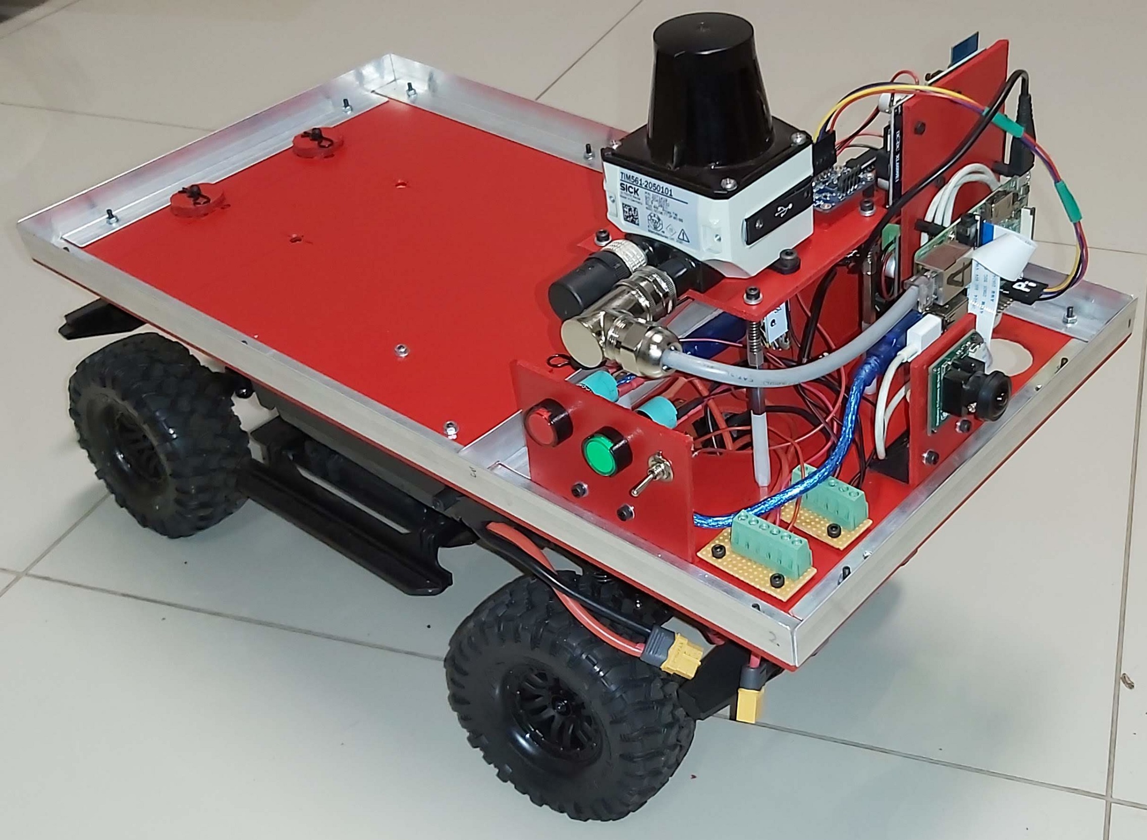
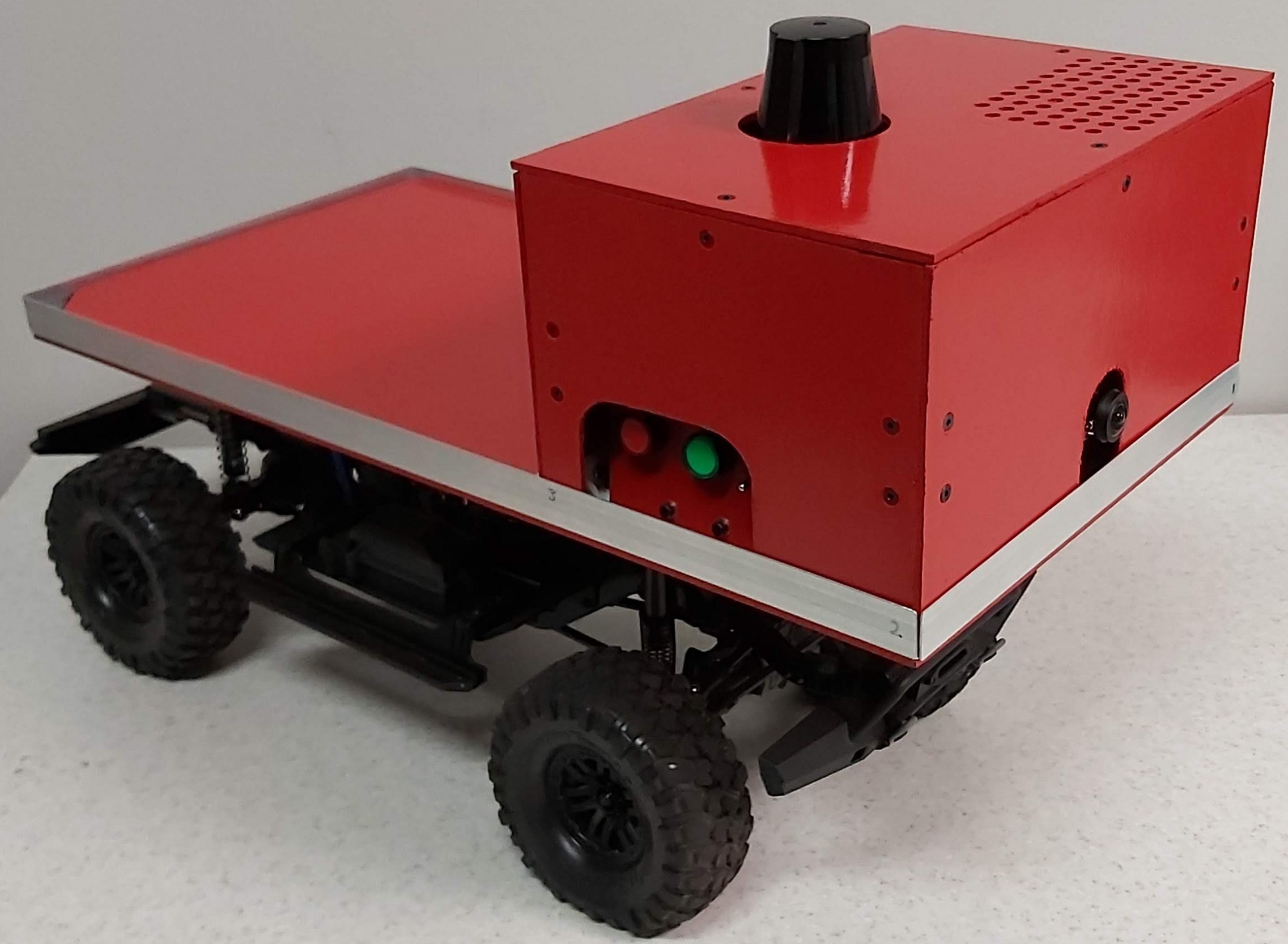
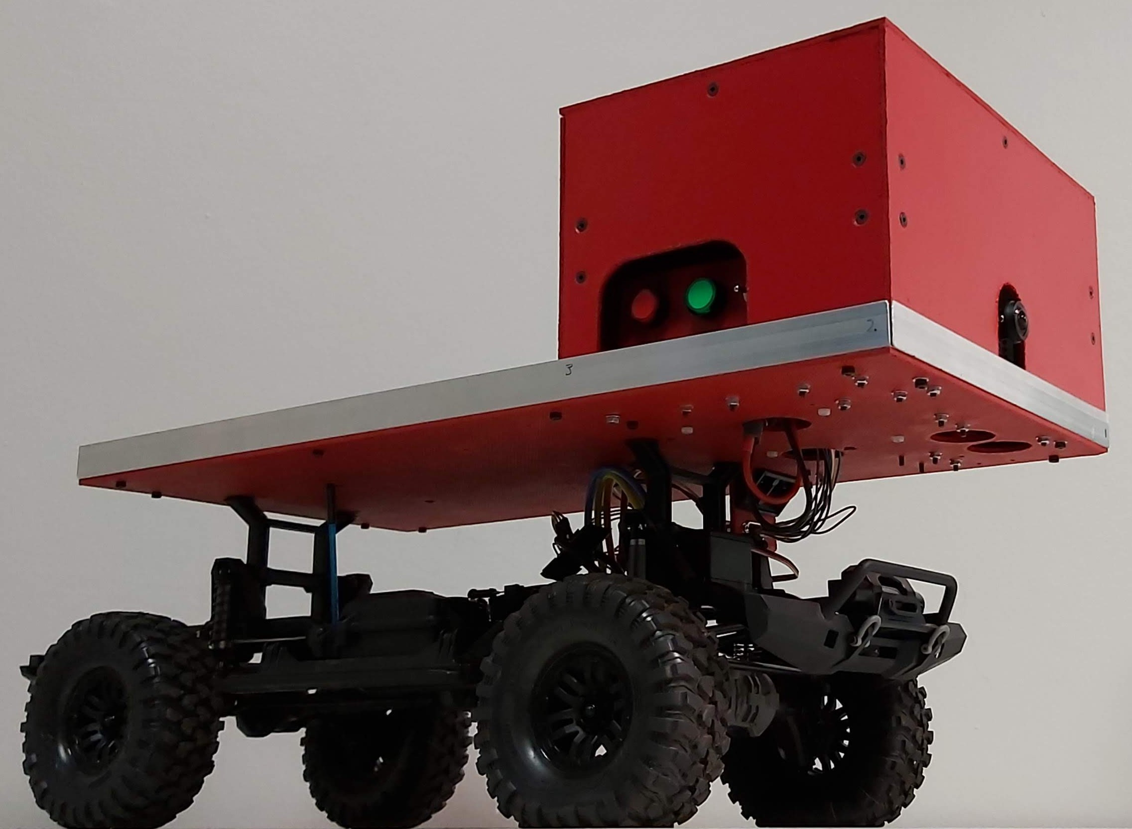
As technical lead of the project, I chose to demonstrate the feasibility of in-house development using a scale prototype. To keep costs low and development velocity high, standard off-the-shelf components such as remote controlled (RC) vehicles and hobby-grade microcontrollers were used for prototyping. The first image below shows a first iteration of the prototype vehicle. Thanks to hardware modularity, this prototype was later easily refactored to mimic the real vehicle more accurately as shown in the following images (see here for comparison).
Simulation
One strong advantage of ROS is its integration with gazebo for simulation.
By the time that the hardware was ready, most of the mapping, planning
and control code had already been set up and tested in simulation.
Gazebo simulated the vehicle odometry, laser scanner, IMU
and camera that were on the vehicle; in some cases, long before the
physical hardware was available. Creating the simulations required
developing .urdf files describing the robot hardware. I
parameterized this as much as possible using .xacro in
anticipation for future refactoring. Hardware and software components
were configured in the simulation phase using roslaunch and
remained handy during transfer to the physical robot. A great deal of the
project revolved around parametrising and setting up these files, I
refer to this as "configuration" throughout.
Integrations
The development process included design, fabrication and software development of both standard and bespoke components. Many aspects were successfully configured in simulation and later transferred to real hardware, allowing unanticipated feature additions without affecting quality or development velocity.
Sensors and Sensor fusion
Since the robot had multiple data streams that were useful for
navigation, a high quality position estimate could be obtained by fusing
these streams using the robot_localization
package, which implements a Kalman filter.
Simultaneous Localization and Mapping (SLAM)
The ROS navigation stack uses OpenSlam as its default
implementation. The real robot's main controller could not handle online
mapping and thanks to ROS's modular publish/subscribe model, it was
simple to move the mapping node to the server side.
Path planning
The navigation stack provides a default global planner, which was
good enough for our needs. This planner doesn’t take into account the
vehicle kinematics and is performed against a static costmap. The
default local planner, however, was replaced with the Timed Elastic Band
local planner (teb_local_planner),
which takes the kinematics of our Ackermann
steering vehicle into account.
Shown below is a simulation of a navigation mission for the robot. The target pose is shown by the purple arrow at the start of the video. The global planner’s path is shown in green and the local planner’s path in red. The output of a simulated camera as well as the simulator’s GUI with a bird’s eye view are shown in separate windows. There are also two plots showing the angular and linear velocity resulting from the navigation commands generated by the navigation stack. The pink/blue shaded area around the vehicle is the costmap taken into account by the local planner which is capable of handling dynamic obstacles.
Control
The main controller runs linux to support
ROS and was not very powerful. This made it inadequate for
the real-time nature of controlling motor speed. Instead, a dedicated
low-level controller was used which ran a PID loop and handled encoder
pulses for speed feedback. On the main controller, the bespoke
interfaces for ros_control were
developed to pass speed and steering angle data back for integration
into pose estimates. Getting odometry data from the standard RC motor
encoder required splicing its signal cable and adding interrupt code to
the low-level controller. For steering angle feedback, I soldered extra
wires onto the servo motor control pot to read its values.
The main controller sent control commands to the low-level controller
using rosserial. I could
not get the C++ rosserial_server to work and
found the codebase stale at the time. Instead, we used the
rosserial_python interface, which worked well from the
get-go. Unfortunately, troubleshooting revealed that teb_local_planner combined with online localization and the
high overhead of the rosserial_python package was too much for the embedded ROS controller.
Visualization and remote control
Another convenient ROS feature is the availability of
various input device capabilities. A joystick, keyboards and software
input devices were configured and used. Rviz is yet another
great advantage of the framework, allowing simultaneous visualization
and interaction with real or simulated robots. The simulation
configuration files of these tools required minimal modifications for
use with the physical vehicle and makes the development process very
tactile and immersive. The video below shows a mapping session using a
joystick as input device from a remote PC. The sensor data streams are
converted to a map of the environment computed and displayed in
rviz on the remote machine using data streams relayed by the
embedded controller. The odometry calculations are also visualized as a
red path trailing the vehicle.
Conclusion
Unfortunately, the project budget was deferred before completion due
to company-wide difficulties resulting in cost cutting and I left the
company soon after. The project revealed that internal development would
be possible given dedicated resources. This is largely made possible due
to open source and the permissively licensed ROS. This was
my first robot and I am proud of how far we had come and the state that
I left the project in.